Resonate Testing supports aircraft fire testing programmes for powerplant components, firewalls, nacelles, fluid systems and equipment installed in designated fire zones, using AC 20-135 guidance and related standards including ISO 2685, RTCA DO-160 Section 26 and SAE AS6826.
FAA AC 20-135 provides guidance for demonstrating aircraft powerplant fire protection compliance, including fireproof and fire-resistant components, firewalls, designated fire zones and systems exposed to fire hazards.
Fire resistant: Demonstrates ability to withstand a 2000°F ±150°F flame for at least 5 minutes while maintaining intended function.
Fireproof: Demonstrates ability to withstand a 2000°F ±150°F flame for at least 15 minutes while fulfilling its design purpose.
Representative installation: Test setup should reflect relevant operating conditions, load paths, airflow, pressure, fluids and interfaces.
Evidence generation: Supports certification by recording flame exposure, leakage behaviour, integrity, ignition risk and required function.
Related methods: Programmes may also reference ISO 2685, RTCA DO-160 Section 26 or SAE AS6826 depending on the component and certification route.
Its Not cabin flammability: AC 20-135 powerplant fire testing is focused on survivability, containment, function and not posing additional risk under severe fire exposure.
Resonate supports aircraft fire testing programmes for powerplant components, firewalls, nacelle structures, fluid systems and equipment installed in designated fire zones. AC 20-135 testing focuses on proving that hardware can resist severe flame exposure while maintaining containment, structural integrity and required function under representative installation conditions.
 FAA AC 20-135 fire protection guidance
ISO 2685 aircraft fire testing
RTCA DO-160 Section 26
SAE AS6826 fire test methods
Customer certification requirements
FAA AC 20-135 fire protection guidance
ISO 2685 aircraft fire testing
RTCA DO-160 Section 26
SAE AS6826 fire test methods
Customer certification requirements
Ready to plan an AC 20-135 fire testing campaign? Send your requirement, drawings, installation assumptions or certification plan for engineer review and receive guidance on fireproof or fire-resistant classification, setup, instrumentation and evidence requirements.
A successful AC 20-135 fire test starts with a signed, revision-controlled test plan and procedure that clearly defines the test article configuration, installation details, pass/fail criteria, instrumentation requirements, and the exact target location on the unit under test (UUT) where burner calibration and fire exposure requirements are to be demonstrated. Establishing these details before testing helps avoid programme delays, specification disputes, and unnecessary retesting.
Before engaging a test laboratory, define the component description, applicable standard, drawings, mounting arrangement, fluid or pressure conditions, required functionality during exposure, and the specific areas of the test article that must satisfy the fireproof or fire-resistant requirements.
Test conditions aft side cooling airflow, fluid temperatures, pressures, flows or mechanical loading and any changes to these parameters after 5 mins during test
When fire occurs in an Aircraft Engine Nacelle, the lives of those on board may depend on giving the pilots time to react safely (fire resistant – 5 mins operability), fire walls containing the event (fireproof- 15 minute) and Fire suppression and isolation, cutting of supply of flammable fluids and extinguishing the event. This can be relied on not because it is simulated but because it is tested during certification and development testing. Proving that critical systems continue to perform their safety function under realistic fire conditions.
Resonate Testing provides specialist aircraft fire testing, aircraft firewall testing, aircraft propulsion fire testing, ISO 2685 testing, SAE AS6826 testing, AC 20-135 fire testing, and RTCA DO-160 Section 26 qualification testing for aerospace OEMs, Tier 1 suppliers, eVTOL developers, battery manufacturers, and aircraft equipment designers. Our capability goes beyond burner exposure by recreating the real operating conditions experienced in service within designated aircraft fire zones. This give the certification authorities the confidence in the test execution to accept and certify the aircraft or component.
| Reference | Typical relevance |
|---|---|
| FAA AC 20-135 | Guidance for demonstrating aircraft powerplant fire protection compliance. |
| ISO 2685 | Environmental fire testing for aircraft components and structures in designated fire zones. |
| RTCA DO-160 Section 26 | Fire and flammability qualification for aircraft equipment categories. |
| SAE AS6826 / customer specifications | Prescriptive fire-test methods, acceptance criteria, monitoring and reporting expectations. |
Testing performed in support of AC 20-135 is intended to demonstrate whether aircraft powerplant components, installations or assemblies can withstand severe flame exposure while maintaining containment, structural integrity and required function. Typical objectives include assessing flame penetration, backside ignition, leakage, deformation, seal performance and post-exposure condition.
Test planning is normally based on the specific component, certification basis and installation assumptions, including fireproof or fire-resistant duration, burner calibration, orientation, pressure or flow conditions, instrumentation, functional checks, observations and reporting expectations.
Resonate supports engineer-led fire testing for aircraft powerplant components, nacelle structures, firewalls, firewall penetrations, fluid systems, electrical equipment and other hardware exposed to designated fire-zone hazards. Programmes can be planned around AC 20-135 guidance, ISO 2685, RTCA DO-160 Section 26 or customer-defined certification requirements.
Typical campaigns assess flame penetration resistance, cold-side ignition risk, leakage containment, structural integrity and continued function where the component must remain operative during or after exposure. Setup is reviewed against the intended installation rather than treated as a generic burn test.
Successful AC 20-135 testing requires more than achieving a nominal flame temperature. Monitoring and verification may include burner calibration, thermocouple data, pressure or flow conditions, leakage observations, functional checks, pre-test inspection and post-test evidence. Acceptance criteria and abort conditions should be agreed before the campaign begins.
For firewalls, ducts, pipes, valves, electrical enclosures and composite structures, the mounting approach is central to the quality of the evidence. Interface drawings, orientation, penetrations, seals, fluid state, airflow and instrumentation access should be reviewed early.
Early engagement helps identify whether the test should demonstrate fire-resistant or fireproof performance, what function must be maintained, and which installation conditions need to be represented.
Component description, drawings, materials and intended installation location
Applicable standard, certification basis and customer specification
Fireproof or fire-resistant classification and required exposure duration
Mounting orientation, interfaces, penetrations, seals and fixture requirements
Pressure, fluid flow, airflow, mechanical loading or operating conditions to represent
Instrumentation needs, thermocouple locations and observation points
Functional checks required during or after exposure
Fuel, oil, hydraulic fluid, pressure, hazardous material or stored-energy safety information
Acceptance criteria for penetration, ignition, leakage, containment and function
Reporting, photographic evidence and witness requirements
For aircraft powerplant fire testing, the concern is often what happens behind or beyond the flame-facing surface. A component may need to prevent flame penetration, avoid cold-side ignition, control hazardous leakage and maintain a required function while exposed to fire.
Containment risk should be reviewed early if the hardware includes fuel, oil, hydraulic fluid, seals, joints, penetrations, pressure boundaries, wiring, composite structures or insulation. The test plan should define how leakage, ignition, deformation and post-test condition will be observed and reported.
Aircraft components often need more than one qualification activity. Coordinating fire, vibration and environmental testing within one campaign helps reduce handover friction, align fixtures and documentation, and keep the engineering review connected across the full programme.
For projects that also need mechanical or environmental testing, review the related services before finalising the campaign sequence, evidence requirements and certification package.
Outputs are agreed before the test so the evidence matches the certification need. A typical package may include:
Recorded flame calibration pre and post test, temperature and BTU (test plan dependant), any UUT telemetry such as pressure, flow and agreed functional data
Evidence showing achieved fire exposure, duration, burner setup and monitoring points
Observations from setup, test execution and post-test review
Photographic evidence of the setup, exposure and post-test condition where agreed
Confirmation of required functional checks completed during or after exposure
An agreed test report or data pack aligned to the acceptance criteria and quotation scope
Testing performed in support of AC 20-135 is intended to demonstrate whether aircraft powerplant components, installations or assemblies can withstand severe flame exposure while maintaining containment, structural integrity and required function. Typical objectives include assessing flame penetration, backside ignition, leakage, deformation, seal performance and post-exposure condition.
Test planning is normally based on the specific component, certification basis and installation assumptions, including fireproof or fire-resistant duration, burner calibration, orientation, pressure or flow conditions, instrumentation, functional checks, observations and reporting expectations.
Resonate supports engineer-led fire testing for aircraft powerplant components, nacelle structures, firewalls, firewall penetrations, fluid systems, electrical equipment and other hardware exposed to designated fire-zone hazards. Programmes can be planned around AC 20-135 guidance, ISO 2685, RTCA DO-160 Section 26 or customer-defined certification requirements.
Typical campaigns assess flame penetration resistance, cold-side ignition risk, leakage containment, structural integrity and continued function where the component must remain operative during or after exposure. Setup is reviewed against the intended installation rather than treated as a generic burn test.
Successful AC 20-135 testing requires more than achieving a nominal flame temperature. Monitoring and verification may include burner calibration, thermocouple data, pressure or flow conditions, leakage observations, functional checks, pre-test inspection and post-test evidence. Acceptance criteria and abort conditions should be agreed before the campaign begins.
For firewalls, ducts, pipes, valves, electrical enclosures and composite structures, the mounting approach is central to the quality of the evidence. Interface drawings, orientation, penetrations, seals, fluid state, airflow and instrumentation access should be reviewed early.
Early engagement helps identify whether the test should demonstrate fire-resistant or fireproof performance, what function must be maintained, and which installation conditions need to be represented.
Fireproof means the component can withstand a 2000°F ±150°F flame for at least 15 minutes while fulfilling its intended design purpose.
It is typically required where the component must continue to provide protection, containment or required function during severe powerplant fire exposure.
Fire resistant means the component can withstand a 2000°F ±150°F flame for at least 5 minutes while maintaining its intended function.
The key difference is exposure duration: fire resistant is typically 5 minutes, while fireproof is typically 15 minutes at the same flame temperature.
A designated fire zone is an aircraft area where fire hazards must be considered, such as engine compartments, nacelles, powerplant installations and related systems.
Examples include firewalls, fluid systems, ducts, electrical equipment, wiring, connectors, latches, hinges, nacelle structures and protected enclosures.
Repeatedly moving the test item between defined hot and cold temperatures to reveal issues such as expansion, contraction, fatigue or changing operating conditions.
Plan: Review the certification basis, component function, applicable standard, fireproof or fire-resistant classification and acceptance criteria.
Prepare: Confirm fixtures, burner configuration, instrumentation, pressure or flow conditions, safety controls and required functional checks.
Mount and instrument: Install the hardware in a representative orientation and verify thermocouples, controls, fluid connections and observation points.
Calibrate and pre-check: Confirm flame temperature, burner position, operating conditions and pre-test condition of the article.
Expose: Apply the agreed fire exposure for the required duration, such as 5 minutes for fire resistant or 15 minutes for fireproof performance.
Observe: Monitor flame penetration, leakage, backside ignition, structural integrity and required function during or after exposure.
Review and report: Compile achieved conditions, observations, photographs, measurements and pass/fail evidence against the agreed criteria.
Component description, drawings, materials and intended installation location
Applicable standard, certification basis and customer specification
Fireproof or fire-resistant classification and required exposure duration
Mounting orientation, interfaces, penetrations, seals and fixture requirements
Pressure, fluid flow, airflow, mechanical loading or operating conditions to represent
Instrumentation needs, thermocouple locations and observation points
Functional checks required during or after exposure
Fuel, oil, hydraulic fluid, pressure, hazardous material or stored-energy safety information
Acceptance criteria for penetration, ignition, leakage, containment and function
Reporting, photographic evidence and witness requirements
Outputs are agreed before the test so the evidence matches the certification need. A typical package may include:
Recorded flame calibration pre and post test, temperature and BTU (test plan dependant), any UUT telemetry such as pressure, flow and agreed functional data
Evidence showing achieved fire exposure, duration, burner setup and monitoring points
Observations from setup, test execution and post-test review
Photographic evidence of the setup, exposure and post-test condition where agreed
Confirmation of required functional checks completed during or after exposure
An agreed test report or data pack aligned to the acceptance criteria and quotation scope
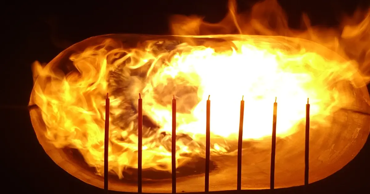
AC 20-135 provides guidance for demonstrating aircraft powerplant fire protection compliance, including fireproof and fire-resistant components, firewalls, nacelles, fluid systems and equipment exposed to fire hazards.
The test helps show whether hardware can resist severe flame exposure without unacceptable flame penetration, hazardous leakage, backside ignition, loss of containment or loss of required function.
Fire resistant performance is typically demonstrated for at least 5 minutes at 2000°F ±150°F. Fireproof performance is typically demonstrated for at least 15 minutes at the same flame temperature.
Yes. The setup should consider mounting, orientation, pressure, flow, airflow, penetrations, seals, structural loading and required function where these affect the certification evidence.
Provide the component description, applicable standard, fireproof or fire-resistant classification, drawings, installation assumptions, operating conditions, instrumentation needs and acceptance criteria.
Typical outputs include achieved fire conditions, observations, photographs, temperature or pressure data where agreed, leakage or ignition findings, functional-check results and a report against the acceptance criteria.
Cabin flammability focuses on flame spread, burn rate and self-extinguishing behaviour. AC 20-135 powerplant fire testing focuses on survivability, containment, leakage prevention and function under severe fire exposure.
Book fire testing for aircraft powerplant components, firewalls, nacelle structures, fluid systems and equipment installed in designated fire zones. Use the contact route to share the requirement, drawings, installation assumptions or certification plan for review.
Whether you’re looking to switch accountants, need advice on a specific issue, or simply want to explore what’s possible — we’d love to hear from you.