
© 2026 ResonateTesting Ltd.
Aircraft fire testing supporting qualification, certification, compliance and engineering validation of propulsion systems, nacelles, thrust reversers, firewalls, fluid systems, wiring and electrical components to ISO 2685, AS6826, AC 20-135 A and Change 1 and RTCA DO-160 Section 26 requirements.
Resonate Testing service supports calibrated fire exposure, flame penetration testing, firewall testing, direct flame impingement, operational system simulation, mechanical loading and dynamic fire testing with vibration where required by the installation environment.
From our clients perspective, it supports type certification, STC programs, qualification testing, design validation, product development, compliance demonstrations, failure investigations and risk reduction.
The correct standard depends on the component, aircraft location, certification basis and route agreed with the relevant customer or authority. Regulations establish the required safety outcome, while standards and advisory material help define the laboratory method and evidence needed to support that outcome.
CS/FAR 25.867 – Fire Protection
Requires systems and structures to provide appropriate protection against fire hazards.
CS/FAR 25.1181 – Designated Fire Zones
Defines which aircraft areas are considered designated fire zones and therefore subject to specific fire protection requirements.
CS/FAR 25.1191 – Firewalls
Specifies requirements for firewalls and firewall installations separating fire zones from protected areas.
CS/FAR 25.1183 – Flammable Fluid Carrying Components
Addresses the fire resistance of components carrying fuel, oil and hydraulic fluids within fire zones.
CS/FAR 25.1193 – Cowling and Nacelle Structure
Requires nacelle and cowling structures to provide adequate fire protection performance.
FAR 33.17 / CS-E 130 – Engine Fire Protection
Defines fire protection requirements for aircraft engines and engine installations.
| Standard / Guidance | Primary Focus | Typical Relevance to Testing |
|---|---|---|
| QS00118 In House Powerplant Fire Test Method | UKAS-accredited in-house aircraft powerplant fire testing methodology covering aircraft powerplant components, firewalls, nacelle structures, hose assemblies and related hardware. | Provides an accredited route for qualification, certification support, compliance demonstrations and development testing within the scope of the UKAS schedule. |
| FAA AC 20-135 / Change 1 | Powerplant fire protection test methods and compliance guidance. | Legacy programme and certification reference that may remain relevant to existing specifications and historic qualification evidence. |
| FAA AC20-135A | Current FAA guidance for aircraft powerplant fire testing and compliance. | Current FAA powerplant fire-testing guidance. It recognises AS6826 as an acceptable Means of Compliance and cancels AC 20-135 Change 1. |
| FAA Engineering Report 3A | Standardised fire-test apparatus, burner design and calibration methodology. | Frequently referenced for burner configuration, flame calibration and fire-test apparatus requirements. |
| ISO 2685 1990 / ISO 2685 1998 | Resistance-to-fire testing of aircraft components, equipment and structures within designated fire zones. | Resistance-to-fire testing for components, equipment and structures located in designated aircraft fire zones. |
| DOT/FAA/AR-00/12 Chapter 11 and DOT/FAA/AR-00/12 Chapter 12 | FAA Aircraft Fire Test Handbook guidance covering hose assemblies and fire penetration testing. | Powerplant hose-assembly and fire-penetration test references. |
| SAE AS1055 / AIR1377 / AS4273 | Fire testing and qualification of aerospace hoses, fittings, tubes and fluid-handling components. | References associated with hoses, tubes, fittings, test equipment and fluid-handling components. |
| SAE AS6826 | Harmonised aircraft powerplant fire-test methodology for fireproof and fire-resistant qualification. | Modern powerplant fire-test standard providing harmonised methodologies and pass/fail criteria for propulsion components and installations. |
| RTCA DO-160G Section 26 | Fire and flammability qualification of airborne equipment and electrical systems. | Fire and flammability requirements for airborne equipment; the applicable category and equipment classification must be reviewed. |
| CS/FAR and engine requirements | Aircraft and engine certification requirements governing fire protection and fire-zone compliance. | Certification context for designated fire zones, firewalls, flammable-fluid components, nacelles, cowling and engine fire protection. |
The correct test route depends on several factors:
ISO 2685 is one of the most widely recognised fire test standards for aircraft powerplant components. It defines methods for evaluating the fire resistance of components, equipment and structures located within designated aircraft fire zones.
SAE AS6826 was developed to provide a more modern and harmonised approach to aircraft powerplant fire testing.
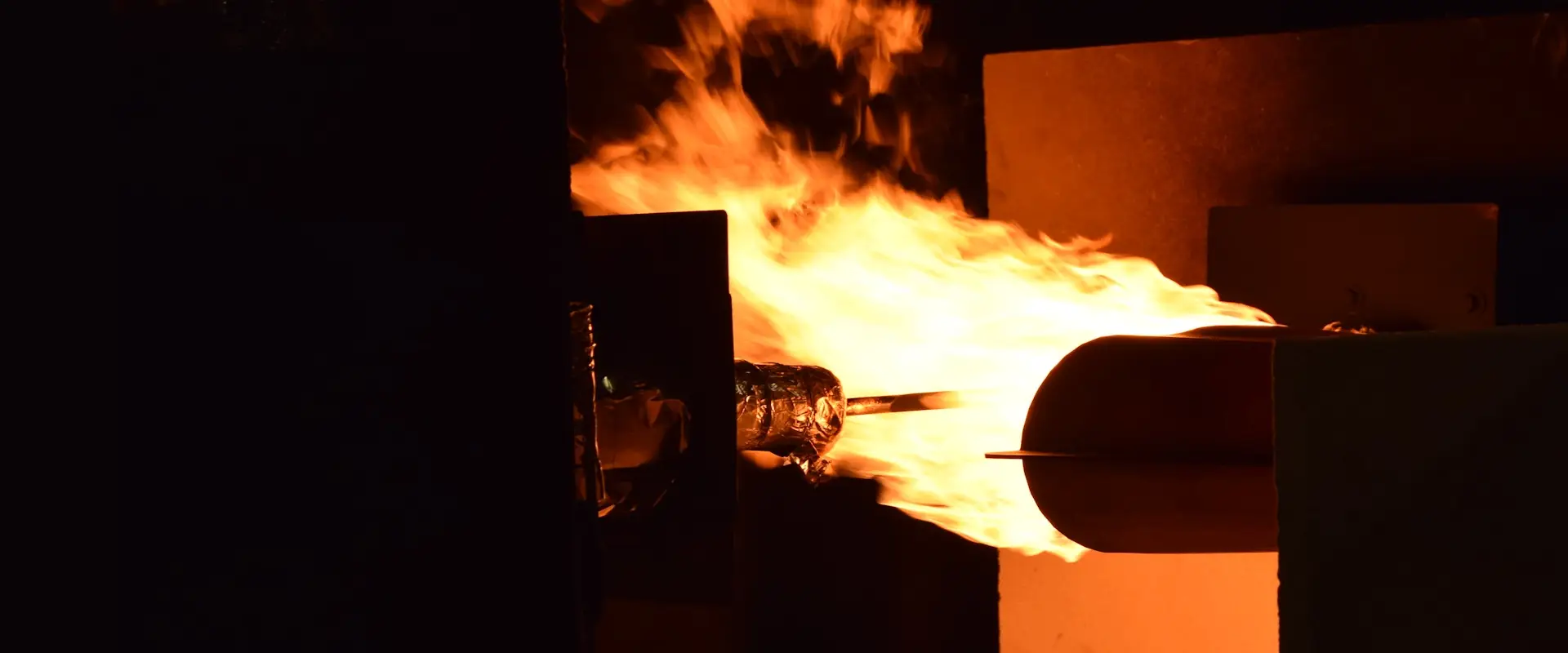
FAA Advisory Circular AC 20-135A provides guidance on demonstrating compliance with aircraft and engine fire protection regulations.
Our capability supports the testing of aircraft propulsion-system components installed within designated fire zones, including nacelles, thrust reversers, firewalls, shrouds, fluid systems, hose assemblies, electrical equipment and engine-zone structures. Programmes can be configured to assess fireproof and fire-resistant performance, flame penetration, leakage, structural integrity, backside ignition and functional continuity under controlled fire exposure.
Test Features
| Specification | Capability |
|---|---|
| Calibrated fire exposure | Kerosene or oil-burner exposure selected and calibrated for the applicable test plan. |
| Fire resistance and fireproof testing | Assessment against agreed duration, operating conditions and acceptance criteria. |
| Firewall and fire penetration testing | Evaluation of barriers, penetrations, seals, joints and representative openings. |
| Nacelle and thrust reverser hardware | Cowling, skins, structures, mechanisms, hinges, latches and adjacent components. |
| Hoses and fluid systems | Fuel, oil, hydraulic, skydrol and other fluid assemblies under agreed pressure, flow and temperature conditions. |
| Representative airflow | “Cooling, differential or installation-related airflow where required by the test basis. |
| Structural and mechanical loading | Loads, restraint systems, fan-cowl hinges and latch arrangements where applicable. |
| Fire with vibration | Simultaneous fire and vibration exposure where required by the installation environment and confirmed during test-plan review. |
| Electrical and pneumatic operation | Electrical loading, functional monitoring, pneumatic pressure and flow where agreed. |
| Instrumentation | Temperature, pressure, flow, vibration, structural and operational-performance monitoring. |
15-Minute Exposure
Withstands a 2000 °F ±150 °F flame for at least 15 minutes whilefulfilling its design purpose.
Applies to firewalls, shrouds and barriers separating designated firezones.
No burn-through or flame penetration for the full exposure duration.
Components must continue to function or fail in a safe, predictablemanner.
Drives longer exposure, more boundary conditions and a longerinstrumented run.
5-Minute Exposure
Withstands the same 2000 °F ±150 °F flame for at least 5 minutes while maintaining intended function.
Typically applied to fluid-carrying lines, hoses and less critical equipment.
Hazardous leakage, ignition and loss of function are the primary failure modes.
Shorter exposure, but the same calibrated flame and set-up discipline.
Test timing and boundary conditions scale to the shorter duration.
The Sonic Burner, also known as the NexGen Burner, is a next-generation oil burner developed by the Federal Aviation Administration (FAA) to replace traditional oil burners used for fire certification tests on aircraft materials. It is designed to provide precise control over fuel and air flow rates, ensuring robust and repeatable flame properties during tests. The NexGen Burner generates a “sooting” flame, which is representative of real-life fire situations, and is capable of achieving flame temperatures of at least 2000°F, making it suitable for evaluating the fire resistance of aircraft interiors and components.
Ignition occurring on the protected side of a component or barrier due to heat transfer through the test article. Backside ignition is commonly assessed during firewall and barrier testing.
The fluid pressures, temperatures, airflow rates, vibration levels, structural loads, electrical loads or pneumatic conditions applied during testing to replicate the real aircraft installation.
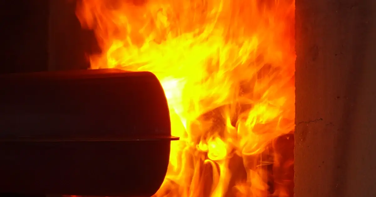
The flame characteristics are common and at it’s simplest; Fire-resistant testing is typically associated with a shorter fire exposure period (5 minutes) where the component must continue to perform its intended function or maintain acceptable safety performance. Fireproof testing is typically associated with a longer-duration requirement (15 Minutes), commonly used where containment, barrier integrity, or continued safety function is critical. The controlling standard, specification, QTP, or certification basis must define the exact requirement.
It is worth noting that the functional requirements applied to the Unit Under Test (UUT), may vary at the transition point which is typically 5 minutes. This is to reflect fire detection, engine shut down at 5 minutes, and the unpowered flight or ground condition be applied for the remaining 10 minutes of the Fire Proof Test.
It provides objective evidence of how an aircraft component performs during a defined fire exposure, including its ability to maintain integrity, containment, attachment or required function under the agreed installation conditions.
SAE AS6826 is a powerplant fire-test standard published in April 2025. FAA AC 20-135A recognises it as an acceptable Means of Compliance for applicable powerplant fire-protection regulations.
Yes, subject to technical review. The service scope includes nacelle skins, cowling, structures, firewalls and propulsion-related mechanisms, with representative loading, airflow, vibration or other operating conditions incorporated where required.
Testing can include representative fluid type, pressure, flow and temperature conditions where required by the installation and test method. The operating limits and safety arrangements must be reviewed before quotation.
Yes, simultaneous fire and vibration exposure can be supported where demanded by the installation environment. The required level, fixture, control method and accreditation position must be confirmed during test planning.
Programmes can include temperature, pressure, fluid flow, vibration, structural and functional-performance monitoring. The final channel list, sensor locations and recording requirements are agreed before testing.
Resonate’s UKAS schedule lists aircraft powerplant component testing under QS00118 for defined products and methods. The accreditation position for every programme, particularly AS6826 or bespoke work, must be confirmed during technical review.
The agreed package may include calibration information, operating-condition data, observations, photographs, deviations, post-test inspection and results against the agreed criteria. Raw data, video, witness records or customer-specific templates can be included where agreed in the quotation. Full certification level reporting can also be provided where agreed.
Whether you’re looking to contact us for the first time or have another testing requirement, we’d love to hear from you.