
© 2026 ResonateTesting Ltd.
BS 3G 100 Explained | History, Significance & Legacy in Aerospace Qualification
Fast, Flexible & Accessible, Your Test Facilitator, not simply a Test facility
BS 3G 100 was not a single test specification. It was a composite suite of British Aerospace Series standards covering general requirements for equipment used in aircraft.
The environmental subsections established standard requirements for test chambers, equipment mounting, operational supplies, atmospheric conditions, functional checks and individual environmental test methods.
BS 3G 100-2.3.0 required environmental tests to use controlled conditions and stated that deviations should be recorded. It also required equipment to be mounted in a way that simulated its normal aircraft installation as closely as practicable.
Supplies and services, including electrical power, air and hydraulic services, were to represent operational use where possible. Equipment was also subject to initial, during-test and post-test performance checks where required by the relevant equipment specification.
The series addressed disciplines including:
vibration
temperature and pressure
temperature-humidity sequences
acceleration and crash loads
tropical exposure
salt mist
waterproofness
fluid contamination
resistance to fire
change of temperature and thermal shock
These requirements reflected environmental and operational challenges that aircraft equipment could encounter during storage, ground operation, flight and emergency conditions.
During the 1950s, 1960s and 1970s, aviation technology was advancing rapidly.
Aircraft were:
flying higher
operating faster
using more sophisticated electrical and electronic equipment
encountering wider temperature and pressure ranges
placing equipment in increasingly demanding installation environments
Qualification practices needed to account for different aircraft classes, equipment locations, operational states and environmental severities.
BS 3G 100 helped provide a common structure through which aircraft designers, equipment manufacturers, approving authorities and test organisations could define and assess qualification requirements.
The temperature-pressure standard grouped aircraft into classes and equipment into grades. Test conditions could then be selected according to aircraft performance, installation region, equipment function and expected operating environment.
The vibration standard used equipment regions, aircraft operating conditions, vibration categories, frequency ranges and exposure durations to construct practical test programmes.
This was not a simple fixed-test philosophy. The relevant equipment specification still had to identify the applicable methods, configuration, operating conditions, severities and acceptance requirements.

The importance of BS 3G 100 lies in its structured treatment of real aircraft environments.
The series connected environmental conditions with:
aircraft type
equipment location
installation configuration
operating state
expected service exposure
failure mechanism
functional performance
acceptance requirements
It did not assume that every item required every test.
The applicable tests had to be selected through the relevant equipment specification. Where standard methods were unsuitable for a particular aircraft, installation or environment, the specification could define additional requirements or modifications.
This created a practical balance between standardisation and engineering judgement.
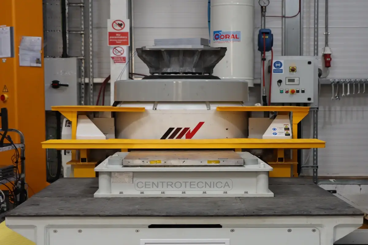
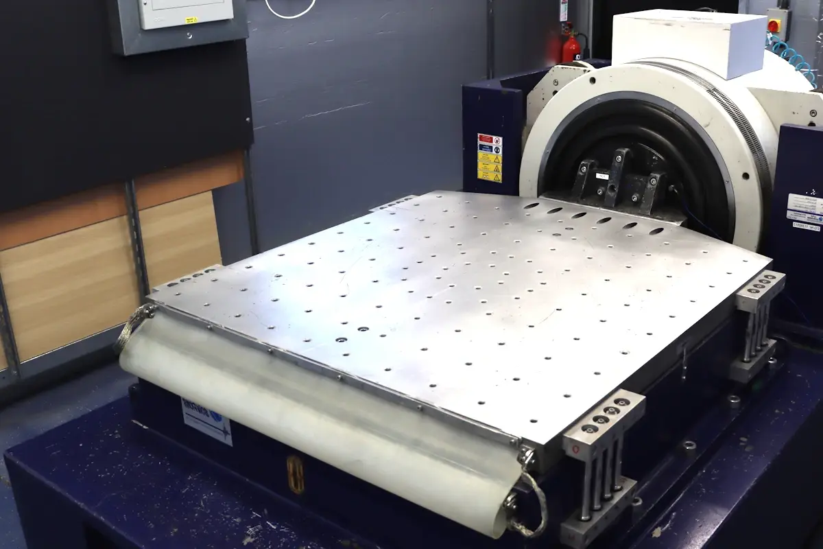
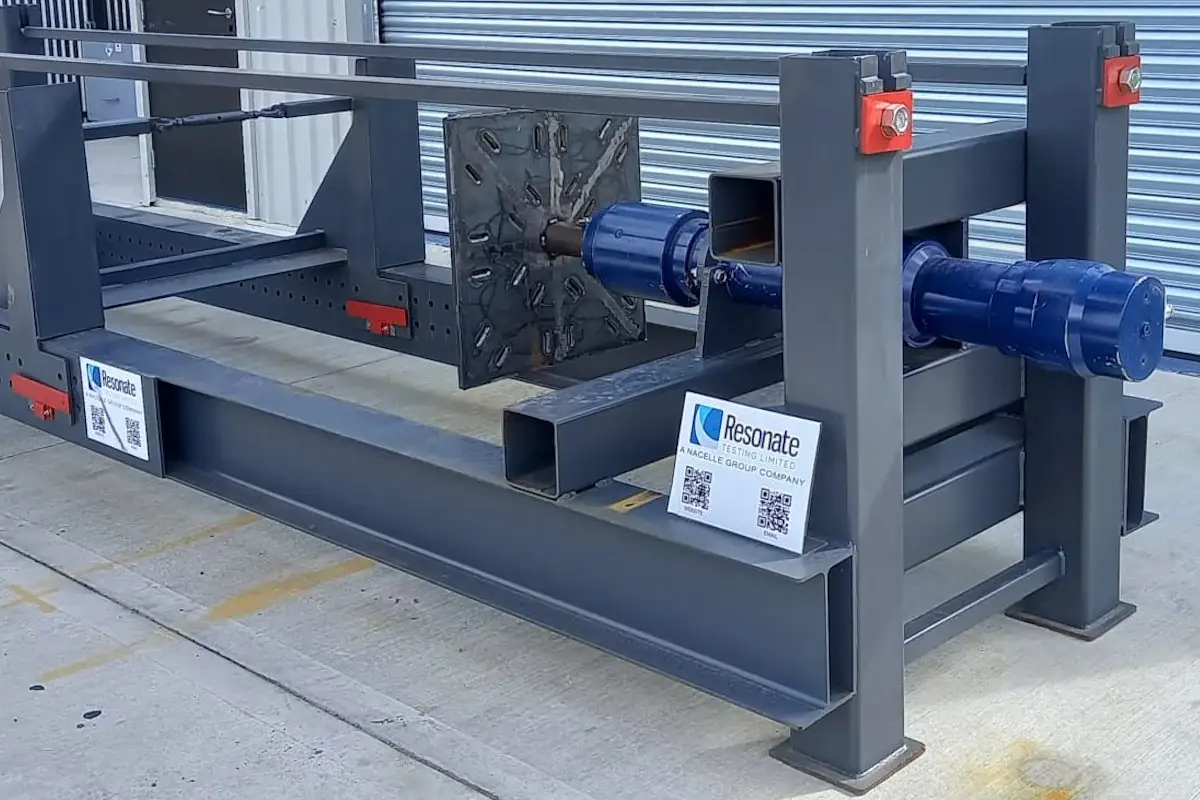
BS 3G 100-2.3.1 addressed complete units of airframe equipment exposed to vibration.
The standard identified two principal concerns:
Mechanical weakness or fatigue damage.
Degradation or malfunction in specified performance.
It divided aircraft installations into equipment regions and linked those regions to flight conditions, vibration categories, frequency ranges and exposure durations.
The preferred test sequence included:
Initial resonance search.
Wide-band random vibration endurance.
Final resonance search.
Alternative routes included narrow-band random sweep, sinusoidal frequency sweep and testing at identified resonance frequencies.
The standard explicitly recognised that vibration testing required engineering judgement. It also stated that random vibration was generally the best representation of an aircraft vibration environment and was therefore preferred for endurance testing.
The mounting arrangement was required to reproduce the operational installation as closely as practicable. Normal attachments, isolators, cables, pipes and other connections had to be considered because they could influence the equipment’s dynamic response.
The standard also recognised that test duration should relate to service exposure, while accepting that a full-life-duration test would often be impractical.
BS 3G 100-2.3.2 defined climatic design and test requirements for aircraft equipment.
It classified aircraft into four broad groups:
rotorcraft and low-performance aircraft
subsonic aircraft
transonic aircraft
supersonic or high-performance aircraft
Equipment grades were linked to installation environments such as:
temperature-controlled and pressurised regions
temperature-controlled but unpressurised regions
uncontrolled or externally exposed locations
engine bays
military aircraft operating at higher speeds or altitudes
The standard included tests for:
low-temperature ground survival
low-temperature ground operation
low-temperature flight operation
temperature-humidity exposure
high-temperature ground survival
short-term high-temperature operation
long-term high-temperature operation
low-altitude high-speed flight
intermediate-altitude operation
high-altitude operation
This structure recognised that aircraft equipment does not experience one universal temperature or pressure condition.
The relevant environment depends upon aircraft performance, installation location, pressure control, temperature control, solar exposure, kinetic heating and equipment-generated heat.
The standard therefore allowed the equipment specification to select the appropriate conditions and modify them where the standard profile did not adequately represent the aircraft or installation.

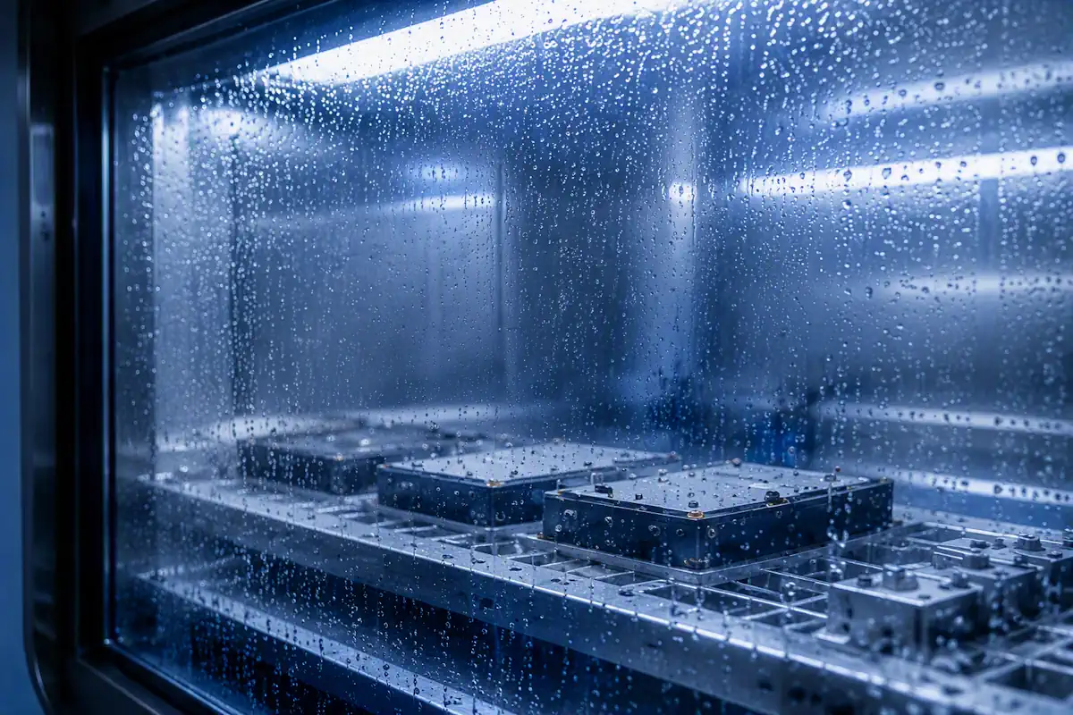

BS 3G 100 recognised that humidity exposure was not limited to prolonged tropical storage.
BS 3G 100-2.3.2 included a temperature-humidity sequence intended to reproduce moisture breathing and condensation associated with an aircraft descending from a cold atmosphere.
The standard recognised that surface moisture could affect electrical circuits. Partially sealed equipment could also draw moist air inside as pressure changed during descent, creating internal condensation and an accumulation of free water.
Three approaches were defined for different equipment constructions and failure risks:
equipment immediately affected by condensation
enclosed equipment vulnerable to cumulative condensation over repeated descents
open equipment affected by condensation where pressure change was less significant
The standard required visible frosting or condensation to occur where applicable. Equipment operation and performance testing were then defined through the relevant specification.
This approach linked the test to a credible flight mechanism rather than treating humidity as an isolated laboratory exposure.
BS 3G 100-2.3.7 addressed equipment installed in aircraft exposed to humid environments typical of tropically wet areas.
The procedure required equipment in its idle state to experience cyclic temperatures between high and lower temperature conditions while relative humidity remained at not less than 95%.
Each cycle lasted 24 hours. The standard test duration was 28 days unless the equipment specification required a longer period.
After exposure, the equipment was examined for deterioration that could impair performance. The relevant equipment specification defined the required performance tests and any permitted recovery conditions.
The standard’s foreword also recorded ongoing work by IEC Technical Committee 50 and ISO Technical Committee 20 to develop internationally agreed and reproducible tropical exposure methods.


BS 3G 100-2.3.6 addressed normal and crash acceleration requirements.
The standard distinguished between equipment that:
must function during and after normal acceleration
must recover immediately after acceleration
must function during and after crash acceleration
may cease functioning but must remain safely attached
Normal acceleration classes reflected aircraft type, installation and manoeuvre.
Crash acceleration requirements considered whether equipment breaking loose could:
injure occupants
obstruct emergency equipment
prevent access to exits
create an additional hazard
Equipment was required to be tested in relevant directions and mounting attitudes. Items capable of being mounted in any attitude were tested in three mutually perpendicular planes and in planes of suspected weakness.
This demonstrates that qualification was not limited to proving that equipment continued to operate. It also considered structural retention and emergency safety.
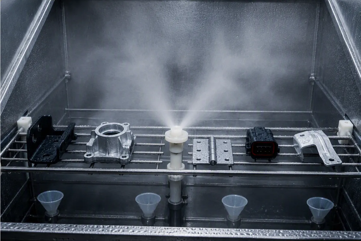
BS 3G 100-2.3.8 defined salt mist tests for two grades of severity.
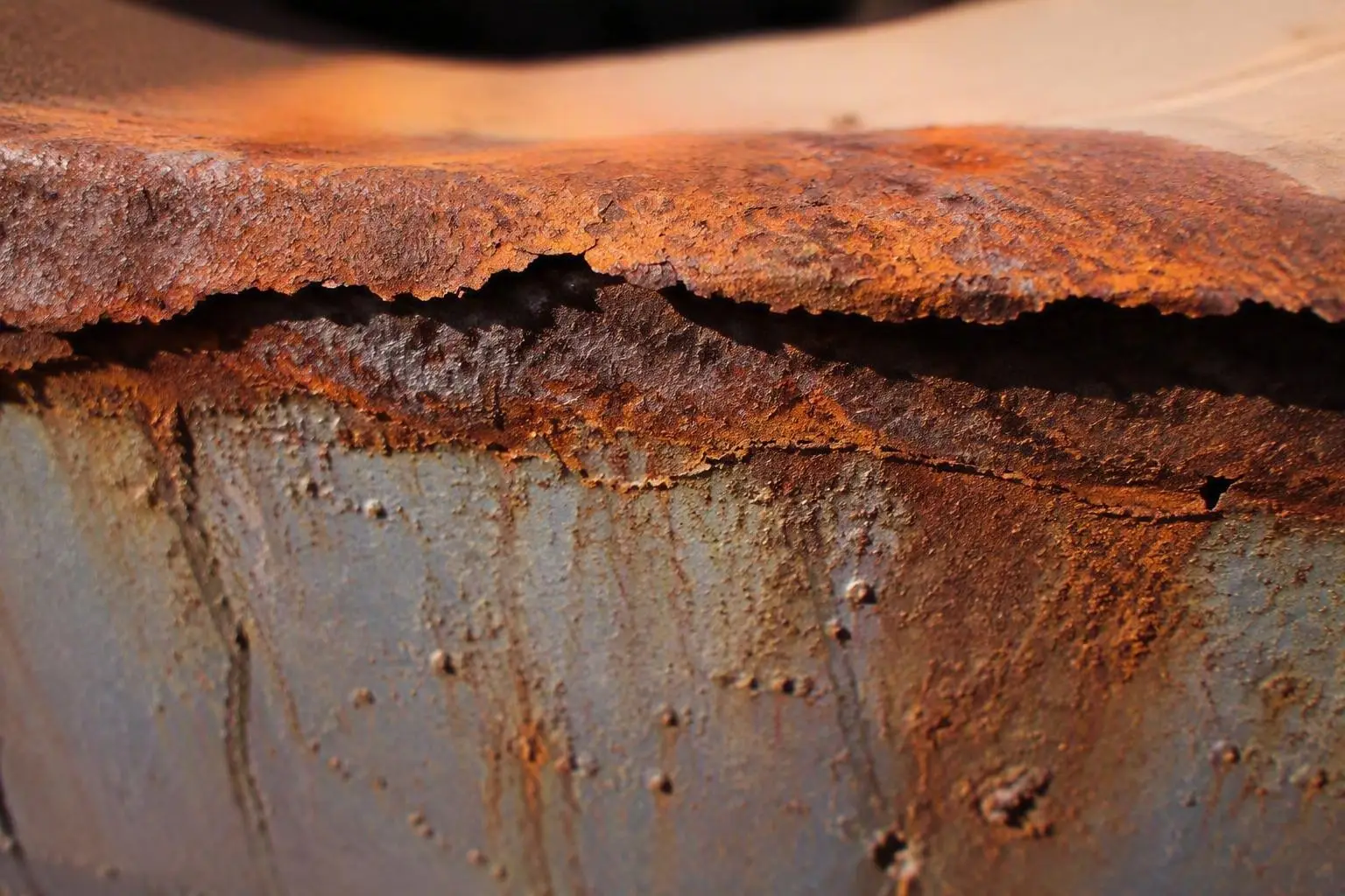
The tests assessed resistance to corrosive salt-laden atmospheres encountered:
at sea
in coastal areas
in certain desert environments
around undercarriage bays
in cabins or equipment bays exposed to occasional salt contamination
Severity 1 applied to demanding contamination conditions such as hovercraft and undercarriage bays.
Severity 2 applied to less exacting locations where salt-laden atmospheres might occur occasionally.
The relevant equipment specification was required to state which severity applied.
The standard also referenced the broader BS 2011 environmental testing framework and recorded continuing IEC and ISO work on internationally reproducible salt mist methods.


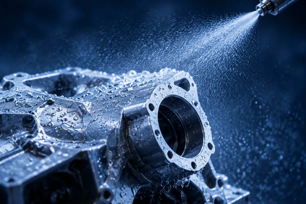
BS 3G 100-2.3.11 specified two grades of waterproofness:
| Grade | Application |
|---|---|
| Grade A: Spray proof | Equipment exposed to driving rain or water spray from different angles |
| Grade B: Drip proof | Equipment exposed to falling moisture or condensation from adjacent aircraft structure |
Grade A testing applied water spray to vulnerable surfaces while the equipment was mounted and configured to represent normal operation.
Grade B testing reproduced water droplets falling onto equipment. The standard specifically recognised condensation falling from neighbouring aircraft structures during the descent of a cold aircraft into a humid atmosphere.
The relevant equipment specification defined:
equipment attitude
operational state
vulnerable surfaces
initial checks
recovery conditions
final examination
electrical and mechanical performance checks
The waterproofness requirements therefore connected test configuration to the actual aircraft installation and expected route of water exposure.
BS 3G 100-2.3.12 assessed whether equipment, materials, components, joints, welds and bonds would be unacceptably affected by contaminating fluids.
The standard identified three exposure classes:
Class A: Occasional contamination
Class B: Intermittent contamination
Class C: Extended contamination
Representative contaminant groups included:
aviation fuels
hydraulic fluids
lubricating oils
solvents and cleaning fluids
de-icing and anti-freeze fluids
runway de-icers
insecticides
waste fluids
dielectric coolants
fire extinguishing agents
The test was not intended to prove that equipment could operate continuously while immersed in a fluid. It was also not intended to demonstrate immunity from electrolytic corrosion.
The equipment specification had to define the test fluid, sample, exposure route, operating condition, temperature, duration, cleaning method and final examination.
The standard encouraged selection of fluids and conditions that represented credible worst-case service situations. It also warned that service fluids could change formulation and that representative standard fluids could improve repeatability between tests.

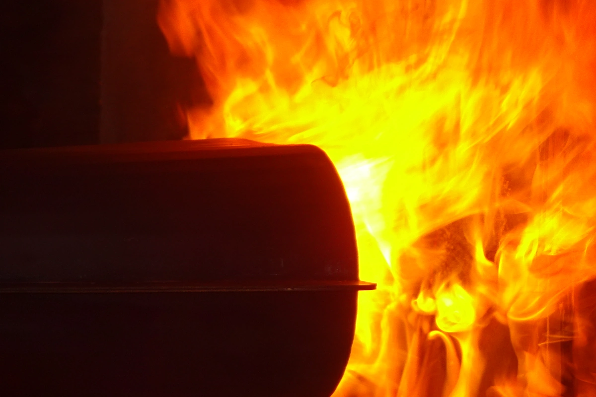
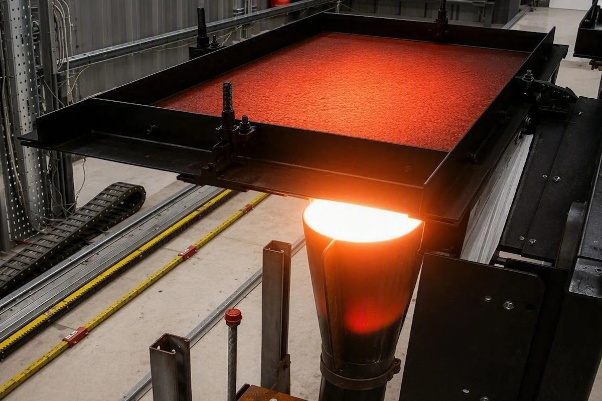
BS 3G 100-2.3.13 addressed equipment and components installed within designated aircraft fire zones.
It defined three grades:
| Grade | Minimum exposure |
|---|---|
| Fire resistant | 5 minutes |
| Fireproof | 15 minutes |
| Torching-flame resistant | 2 minutes |
The standard flame had a nominal temperature of 1,100°C. It included burner arrangements, flame calibration requirements, mounting conditions, vibration requirements and operational test conditions.
The test article had to be mounted in a manner no less critical than the aircraft installation.
Unless otherwise specified, units were also vibrated during the fire test. The standard identified a nominal frequency close to 50 Hz, with defined amplitudes for general equipment and flexible hose assemblies.
The test procedure considered both initial critical operating conditions and the conditions that could exist after completion of an engine fire drill.
The standard distinguished resistance to fire in designated fire zones from general flammability requirements. These were not treated as the same qualification question.
BS 3G 100-2.3.15 addressed temperature variation and thermal shock.
The standard was published as identical to ISO 2657:1976, Environmental Tests for Aircraft Equipment, Part 2.7: Change of Temperature.
Two categories were defined:
Category A: Temperature variation
Category B: Thermal shock
Category A used a controlled rate of temperature change within a chamber. It simulated temperature changes associated with aircraft climb and descent.
Category B transferred equipment between hot and cold chambers. It was intended to simulate rapid temperature changes, including kinetic heating effects in high-speed aircraft.
The equipment specification had to define:
the test method
whether performance or survival was being demonstrated
operating phases
temperature sequence
number of cycles
transfer time
equipment category
temperature limits
rate of temperature change
exposure duration
The standard recognised that thermal effects could produce fracture, seizure, differential expansion, contraction or changes in electrical performance.
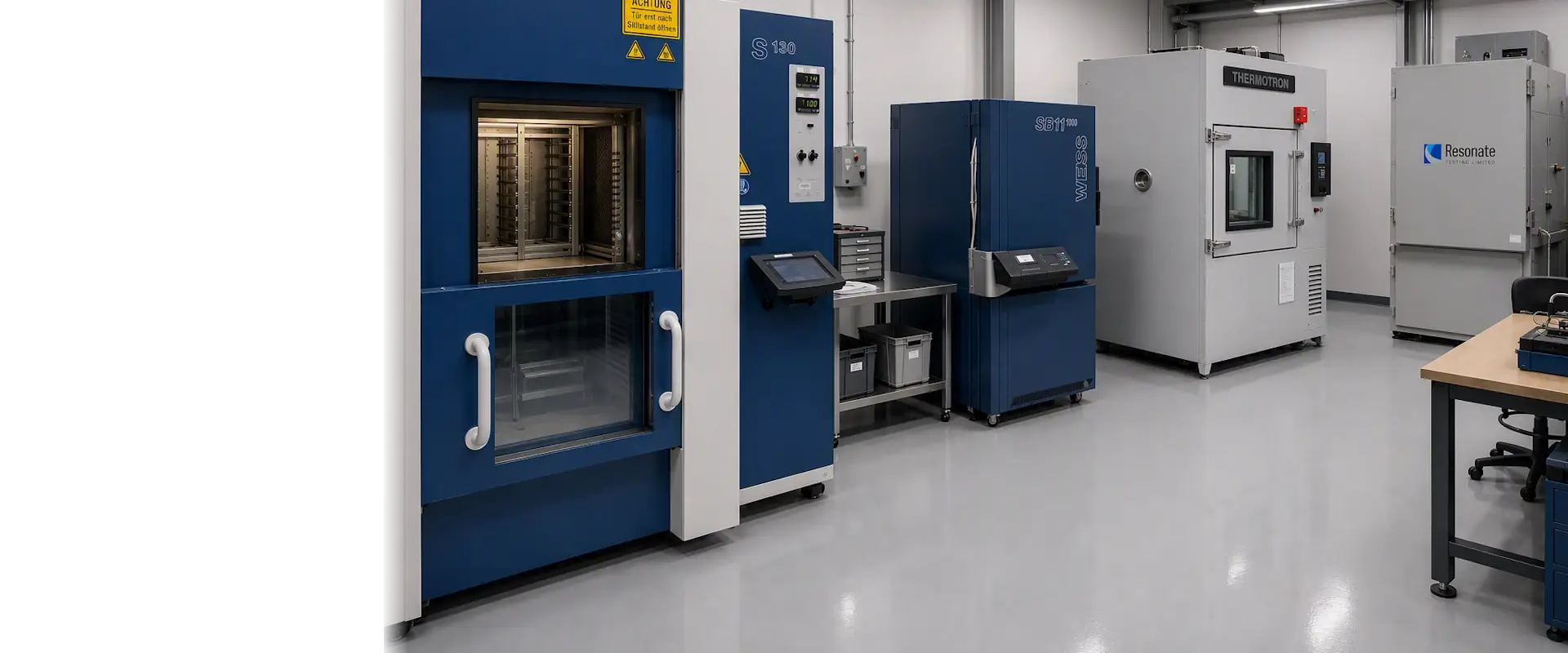
Resonate testing provides high quality fire, mechanical, and environmental test solutions and certification services across a wide range of industrial sectors. From Primes to SME’s, Resonate Testing provides a bespoke and tailored service to our clients.
| Subsection | Environmental subject |
|---|---|
| 2.3.0 | Standard test requirements |
| 2.3.1 | Vibration |
| 2.3.2 | Temperature and pressure |
| 2.3.6 | Acceleration requirements |
| 2.3.7 | Tropical exposure |
| 2.3.8 | Salt mist |
| 2.3.11 | Waterproofness |
| 2.3.12 | Fluid contamination |
| 2.3.13 | Resistance to fire in designated fire zones |
| 2.3.15 | Change of temperature and thermal shock |
Together, these subsections formed a broad aircraft equipment environmental qualification framework.
The series combined common laboratory controls with individual test methods and equipment-specific requirements. This allowed standardisation without assuming that every aircraft, installation or item of equipment faced the same environment.
The BS 3G 100 documents record repeated interaction with international standardisation activity.
Examples include:
BS 3G 100-2.3.0 partially complying with draft ISO 2650.
BS 3G 100-2.3.6 anticipating international agreement through ISO Technical Committee 20.
BS 3G 100-2.3.7 referring to IEC Technical Committee 50 and ISO Technical Committee 20 work on tropical exposure.
BS 3G 100-2.3.8 referring to IEC and ISO work on salt mist test reproducibility.
BS 3G 100-2.3.11 reflecting the technical content of a draft ISO standard.
BS 3G 100-2.3.15 being published identically to ISO 2657:1976.
This evidence shows that BS 3G 100 was part of a wider transition from national aerospace standards towards increasingly international test methods and terminology.
It would, however, be inaccurate to claim that every modern aerospace standard was directly derived from BS 3G 100. Similarity, alignment and participation in international standardisation do not by themselves prove direct derivation.
The defensible conclusion is that BS 3G 100 documents an important stage in the development and international alignment of aircraft environmental qualification practice.
For engineers, students, certification specialists and test professionals, BS 3G 100 remains a valuable learning resource.
The series shows how temperature, pressure, humidity, vibration, acceleration, water, fluids, corrosion and fire can affect aircraft equipment.
It connects environmental exposure to failure mechanisms including fatigue, fracture, corrosion, seal degradation, moisture ingress, material swelling, electrical malfunction and loss of structural retention.
It explains why tests are selected, how equipment location changes severity and why operational configuration matters.
The documents record the transition from earlier British requirements towards more structured and internationally aligned environmental test methods.
The series connects the aircraft environment, equipment design, installation, operation, safety and acceptance evidence.
The value of BS 3G 100 therefore extends beyond historical interest. It provides a practical framework for understanding how qualification engineers translate service environments into controlled test evidence.
Resonate testing provides high quality fire, mechanical, and environmental test solutions and certification services across a wide range of industrial sectors. From Primes to SME’s, Resonate Testing provides a bespoke and tailored service to our clients.
BS 3G 100 represents more than a collection of historical aerospace test standards.
It established a structured and engineering-led approach to aircraft equipment qualification.
The series connected environmental testing with:
aircraft classification
equipment location
operating condition
installation configuration
service exposure
functional performance
failure mechanisms
safety requirements
acceptance evidence
Its individual subsections addressed vibration, temperature, pressure, humidity, acceleration, tropical exposure, salt mist, waterproofness, fluid contamination, fire resistance and thermal shock.
The series also records the growing alignment of British aerospace standards with ISO and IEC activity.
Its central engineering lesson remains valid:
Understand the environment. Understand the failure mechanism. Demonstrate performance and survival before flight.
For anyone studying aerospace qualification, environmental engineering or the evolution of aircraft equipment standards, BS 3G 100 remains essential technical reading.
Your Test Facilitator. Not simply a test facility.
Use the contact route to share the requirement, test profile, drawings or specification for review.
Whether you’re looking to contact us for the first time or have another testing requirement, we’d love to hear from you.